The XY stage of the machine is a critical part. It must be efficient, accurate, and stiff. I spent many hours refining the design and running simulations. Pictured below is the end result. I decided to purchase a 670mm rolled ball screw from Automation Technologies for the X axis along with THK HSR25 linear rails and pillow blocks. The Y axis mounts directly on top and uses the SR20 rail, pillow blocks, and Areotech ground ball screw. Both axes use the NEMA 34 steppers mentioned earlier.
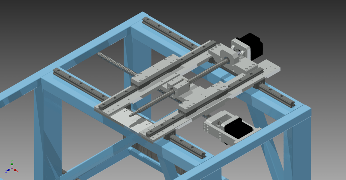
Below is a top view of the XY axes. The design resulted in 19 x 15 inches (X x Y) of travel. The aluminum section that the SR20 rail on the right mounts to is longer so IGUS energy chain can be mounted. You may also notice that both of the ball screws are unsupported on the non-drive end, this is to reduce the number of parts that need machined. The design allows for supports to be implemented if deemed necessary during manufacturing/ assembly process.
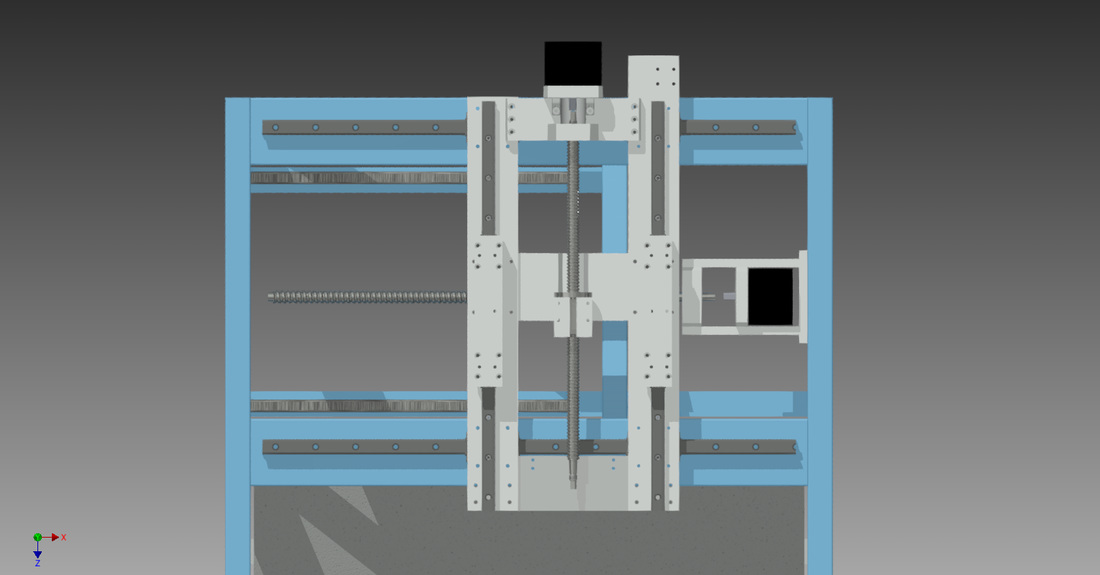
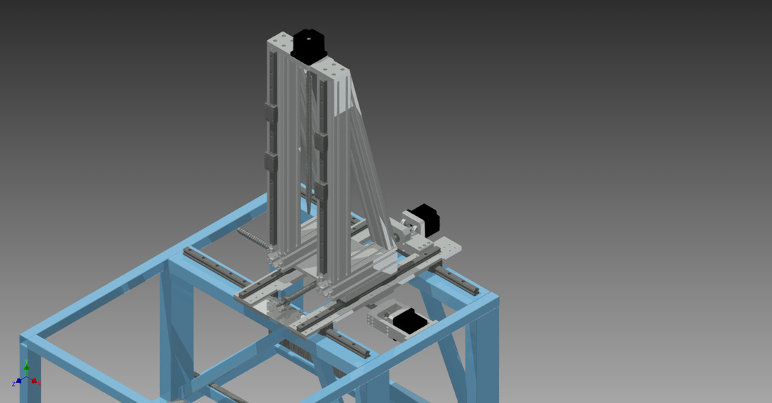
Z Axis
In order to accommodate the needs of 5 axis machining and a variety of tooling the Z axis must very tall. I decided to purchase a longer THK SR20 Rail off eBay and use 15 series 80-20 aluminum extrusions. Here are the results. (some ball screw mounting still pending)
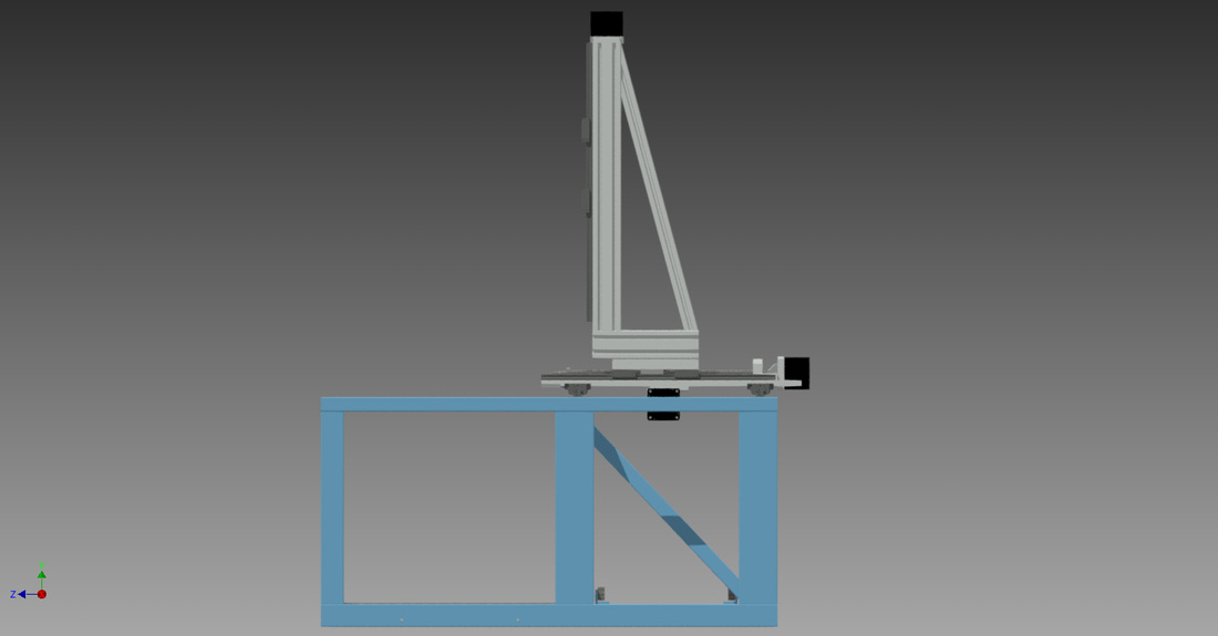
He is a side view, showing the rear triangle. I ran stress and frame anylisis to verify the machine will remain in tolerance under the forces exerted by machining. (I think it will, simulations can only tell me so much)
 RSS Feed
